Wednesday, June 25, 2008

3 W FM TRANSMITTER

This is the schematic of the 3W FM Transmitter

Parts

Part
Total Qty.
Description
Substitutions
R1,R4,R14,R15410K 1/4W Resistor
R2,R3222K 1/4W Resistor
R5,R1323.9K 1/4W Resistor
R6,R112680 Ohm 1/4W Resistor
R71150 Ohm 1/4W Resistor
R8,R122100 Ohm 1/4W Resistor
R9168 Ohm 1/4W Resistor
R1016.8K 1/4W Resistor
C114.7pF Ceramic Disc Capacitor
C2,C3,C4,C5,C7,C11,C127100nF Ceramic Disc Capacitor
C6,C9,C10310nF Ceramic Disc Capacitor
C8,C14260pF Trimmer Capacitor
C13182pF Ceramic Disc Capacitor
C15127pF Ceramic Disc Capacitor
C16122pF Ceramic Disc Capacitor
C17110uF 25V Electrolytic Capacitor
C18133pF Ceramic Disc Capacitor
C19118pF Ceramic Disc Capacitor
C20112pF Ceramic Disc Capacitor
C21,C22,C23,C24440pF Trimmer Capacitor
C2515pF Ceramic Disc Capacitor
L115 WDG, Dia 6 mm, 1 mm CuAg, Space 1 mm
L2,L3,L5,L7,L956-hole Ferroxcube Wide band HF Choke (5 WDG)
L4,L6,L831.5 WDG, Dia 6 mm, 1 mm CuAg, Space 1 mm
L1018 WDG, Dia 5 mm, 1 mm CuAg, Space 1 mm
D11BB405BB102 or equal (most varicaps with C = 2-20 pF [approx.] will do)
Q112N3866
Q2,Q422N2219A
Q31BF115
Q512N3553
U117810 Regulator
MIC1Electret Microphone
MISC1PC Board, Wire For Antenna, Heatsinks

BOSTER FM 30 Watt


Circuit Linear FM 30Watt

Linear FM 30Watt

PARTS

C1, C2, C3, C4 = 10 -80pF

C 5 = 10nF

C6 = 1000pF

C7 = 100nF

C8 = 2200mF/35V

L1 = 1 coil with diameter of 10 mms, 1 mm

L2 = 7 coils with diameter of 10 mms, 0,8 mm

L3 = 3 coils with diameter of 10 mms, 1 mm

TR1 = BLY89

RFC = RF tsok


pcb Linear FM 30Watt

4 W FM TRANSMITTER

1028.gif (36983 bytes)

This is a small but quite powerful FM transmitter having three RF stages incorporating an audio preamplifier for better modulation. t has an output power of 4 Watts and works off 12-18 VDC which makes it easily portable. It is the ideal project for the beginner who wishes to get started in the fascinating world of FM broadcasting and wants a good basic circuit to experiment with.

Modulation type: ........ FM
Frequency range: .... 88-108 MHz
Working voltage: ..... 12-18 VDC
Maximum current: ....... 450 mA
Output power: ............ 4 W

Electronic Diagram.

fm1_th.gif (5702 bytes)


Parts List

R1 = 220K
R2 = 4,7K
R3 = R4 = 10K
R5 = 82 Ohm
R = 150Ohm 1/2W x2 *
VR1 = 22K trimmer

C1 = C2 = 4,7uF 25V electrolytic
C3 = C13 = 4,7nF ceramic
C4 = C14 = 1nF ceramic
C5 = C6 = 470pF ceramic
C7 = 11pF ceramic
C8 = 3-10pF trimmer
C9 = C12 = 7-35pF trimmer
C10 = C11 = 10-60pF trimmer
C15 = 4-20pF trimmer
C16 = 22nF ceramic *

L1 = 4 turns of silver coated wire at 5,5mm diameter
L2 = 6 turns of silver coated wire at 5,5mm diameter
L3 = 3 turns of silver coated wire at 5,5mm diameter
L4 = printed on PCB
L5 = 5 turns of silver coated wire at 7,5mm diameter

RFC1=RFC2=RFC3= VK200 RFC tsok

TR1 = TR2 = 2N2219 NPN
TR3 = 2N3553 NPN
TR4 = BC547/BC548 NPN
D1 = 1N4148 diode *
MIC = crystalic microphone

STEREO FM TRANSMITTER


CIRCUIT BOARD
Dimensions of the PCB should be 57 mm x 35 mm (W x H).

FM TRANSMITTER 0,4 W

Power supply: 12-14 V stab., 100 mA
RF power: 400 mW
Impedance: 50-75 ohm
Frequency range: 87,5-108 MHz
Modulation: wideband FM

Schematic diagram

tx1.gif (5874 bytes)

Parts list

Capacitors:
C1, C2, C12 - 100 pF (ceramic)
C3, C5 - 0,22 uF (electrolytic)
C4 - 1,8 nF (plastic)
C13, C16, C17, C19 - 1 nF (ceramic)
C8, C9 - 10 pF (ceramic)
C10 - 47 pF (ceramic)
C11 - 8,2 pF (ceramic)
C14 - 60 pF trimmer
C15 - 35 pF trimmer
C18, C7 - 100 nF (ceramic)
C20 - 470 uF (electrolytic, 16 V)

Coils:
(All coils are free-standing air-core types, wound of 0,7 mm Cu wire, 6 mm internal diameter.)
L1 - 4,5 coils
L2 - 9,5 coils
L3 - 4,5 coils

Resistors:
R1, R2 - 10 k pot.
R3 - 33 k
R4, R7, R12 - 10 k
R5, R11 - 470
R6 - 27 k
R8 - 22 k
R9 - 270
R10 - 100

Misc.:
D1 - BB409 (BB109G, BBY31) varicap
T1 - BC547C (BC548C, BC547B)
T2 - BFR91A (BFR96)
T3 - BFR96

Antenna
Power supply
3,5 mm jack
CD player, computer
6 V / 0,1 A bulb

PCB LAYOUT

tx1dps1.gif (7280 bytes)

tx1dps2.gif (2133 bytes)

PLL FM TRANSMITTER 1W

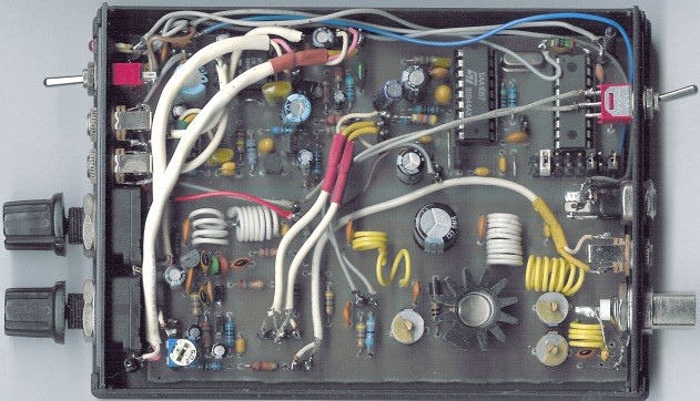
This small FM transmitter includes a limiter, a microphone amplifier and a PLL digital tuning. All the parts are placed on one circuit board. The RF power is switchable between 1 W (HI) and 0,2 W (LO).

tx3.jpg (87806 bytes)

Technical specifications

Supply voltage: 12 V from accumulator or regulated power supply
Supply current (HI/LO): 270/170 mA
RF power HI: 1 W
RF power LO: 0,2 W
Impedance: 50-75 ohm
Frequency range: 87,5-108 MHz
Modulation type: wide-band FM
Modulation inputs: line, mic, RDS/MPX
PCB dimensions: 11,3 x 8,8 cm

RF part 1 W

tx3vf.gif (7338 bytes)

Resistors:
R1 - pot. 5 k
R2, R12 - 1 k
R3 - 220
R4, R8, R10 - 27 k
R5, R6, R14, R17 - 10 k
R7, R16 - 470
R9 - 100
R11 - 270
R13 - 10
R15 - 22 k

Capacitors:
C1 - 4,7 uF
C2 - 1 uF
C3, C4, C12 - 100 pF
C6, C9, C11, C13, C14, C19, C22 - 1 nF
C7, C8 - 10 pF
C10 - 8.2 pF
C18 - 22 pF
C15 - trimmer 47 pF
C16, C17 - trimmer 60 pF
C20, C5 - 100 nF mini
C23 - 470 uF

Coils:
(All coils are free-standing air-core types, wound of 0,7 mm Cu wire, 6 mm internal diameter.)
L1 - 4,5 coils
L3 - 2,5 coils
L4 - 1,5 coils
L2 - 6,5 coils around R9 resistor
L5 - 9,5 coils
L6 - 5,5 coils
L7 - 3,5 coils

Diodes:
D1, D2 - BB109G, BBY31 or BB409

Transistors:
T1 - BC547C (BC548C, BC547B)
T2 - BFR91A (BFR96)
T3 - BFR96
T4 - 2SC1971

Misc:
S1 - switch

PLL digital tuning

tx3pll.gif (9225 bytes)

Resistors:
R31 - 1k
R32 - 4k7
R33, R37 - 10k
R34, R35 - 1k
R36 - 470
R38 - 47k

Capacitors:
C31, C42 - 2,2 nF
C32, C40 - 10 nF
C33 - 47 uF
C34 - 10 uF tantal
C35 - 0,47 uF
C36, C41 - 100 nF
C37 - 1 nF
C38 - 220 uF
C39 - 22 pF

Misc:
IC31 - SAA1057
IC32 - PIC16F84-04 + socket
IC33 - 78L05
X31 - 4 MHz crystal
D31 - LED diode
Tl31 - button
Jumpers 2x8 pins or DIP switches

Audio and power supply part

tx3audio.gif (9200 bytes)

Resistors:
R51, R52 - pot. 5 k
R53, R58, R64 - 10 k
R54, R55 - 22 k
R56 - 56 k
R57 - 1,5 k
R59 - 180 k
R60 - 820
R61 - 10 M
R62 - 47
R63 - 240 k

Capacitors:
C51, C54 - 100 pF
C52, C57 - 2,2 uF
C53 - 1 uF
C55, C62, C63 - 10 uF
C56, C64 - 47 nF
C58 - 1 nF plastic
C59, C60 - 1 uF tantal 25 V
C61 - 100 uF
C65 - 150 nF
C66, C67, C68, C70 - 10 nF
C69 - 470 uF

Misc:
T51 - BF245C
T52 - BC556B
IC51, IC52 - LM386
S51 - switch

Complete parts list

Resistors:
1x 10
1x 47
1x 100
1x 270
2x 220
3x 470
1x 820
5x 1k
1x 1,5 k
1x 4,7 k
9x 10 k
3x 22 k
3x 27 k
1x 56 k
1x 47 k
1x 180 k
1x 240 k
1x 10 M
3x pot. 5 k log.

Capacitors:
1x 8,2 pF
2x 10 pF
3x 22 pF
5x 100 pF
8x 1 nF
1x 1 nF plastic
2x 2,2 nF
5x 10 nF
2x 47 nF
4x 100 nF mini
1x 150 nF
1x 0,47 uF
2x 1 uF
2x 2,2 uF
1x 4,7 uF
4x 10 uF
1x 47 uF
1x 100 uF
1x 220 uF
2x 470 uF
2x 1 uF tantal
1x 10 uF tantal
1x trimmer 47 pF
2x trimmer 60 pF

Semiconductors:
1x BC547C (BC548C, BC547B)
1x BFR91A
1x BFR96
1x 2SC1971
1x BC556B
1x BF245C
2x LM386
1x SAA1057
1x PIC16F84A-04 + socket
1x 78L05
1x Yellow LED 3 mm
2x BB109G, BBY31 or BB409

Misc:
1x 4 MHz crystal
2x switch
1x button
1x jumpers 2x8 pins or DIP switches
1x power supply connector
3x jack 3,5 mm
1x antenne connector
1x plastic case
thin shielded cables

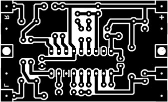
PRINTED CIRCUIT BOARD

tx3dps2.gif (23483 bytes)

tx3dps.gif (27933 bytes)


MINIATURE FM TRANSMITTER


Parts List
R1,R4,R6 = 10K C1,C2 = 0.1uF Q1,Q2 = 2N3904
R2 = 1M C3 = 0.01uF L1 = 0.1uH
R3 = 100K C4 = 4-40pF
R5 = 100 ohm C5 = 4.7pF
R7 = 1K
Construction
This miniature transmitter is easy to construct and it's transmissions can be picked up on any standard FM radio. It has a range of up to 1/4-mile (400 meters) or more, depending on the line-of-sight, obstructions by large buildings, etc. It is great for room monitoring, baby listening, nature research, etc.
L1 is 8 to 10 turns of 22 gauge hookup wire close wound around a non-conductive 1/4-inch diamter form, such as a pencil.
C4 is a small, screw-adjustable, trimmer capacitor.
Set your FM radio for a clear, black space in the lower end of the band (88MHz). Then, with a non-metallic/non-conductive trimmer tool, adjust this capacitor for the clearest reception. A little experimenting and patience may be in order.
Most of the parts values are not critical, so you can try adjusting them to see what happens.

If you decide to substitute transistors with something similar you already have, it maybe necessary adjust the collector voltage of Q1 by changing the value of R2 or R3 (because you change transistors, it changes this bias on the base of Q1). It should be about 1/2 the supply voltage (about 4 or 5v).

Notes
The default for the capacitors type is ceramic, preferably the npo 1% (low noise) type or equivalent. But basically nothing critical here. Use any capacitor you have laying around, but NO electrolytic or tantalum caps. Only if you intend to use this circuit outside the home you may want to select more temperature stable capacitors.

To find the signal on your receiver, make sure there is a signal coming into the microphone, otherwise the circuit won't work. I use an old mechanical alarm clock (you know, with those two large bells on it). I put this clock by the microphone which picks up the loud tick-tock. I'm sure you get the idea... Or you can just lightly tap the microphone while searching for the location of the signal on your receiver.